10 kV / 35 kV three-phase oil distribution transformer TMG
S11 35kV 38.5kv 0.4kv Electric Oil Power Transformer T-12S11-35KV refers to a type of electrical transformer. The "S11" designation typically indicates a three-phase oil-immersed distributio
S11 35kV 38.5kv 0.4kv Electric Oil Power Transformer T-12S11-35KV refers to a type of electrical transformer. The "S11" designation typically indicates a three-phase oil-immersed distributio
•We develop
design and technical documentation
•We manufacture
electrical equipment of any complexity
•We deliver
equipment fully factory-ready
•We install
and connect equipment at the destination
•We service
equipment during and after the warranty period
10kV/35kV Three-Phase Oil-Immersed Distribution Transformer
Capacity: 63kVA–2500kVA, 15kVA–315000kVA
Voltage: 6, 10, 15, 20, 30, 35kV
Types: S9, S11, S12, S13, S20, S33
Application:
The oil-immersed transformer is suitable for voltage levels from 6kV to 35kV and power ratings from 15kVA to 31500kVA, meeting the needs of various application scenarios.
Description:
This series of three-phase oil-immersed transformers adopts a fully sealed corrugated oil tank, which utilizes the elasticity of oil to accommodate expansion and ensure effective heat dissipation. The tank body features a new insulation structure that enhances short-circuit resistance. The core is made of high-quality cold-rolled silicon steel sheets.
The high- and low-voltage windings are made of oxygen-free copper with a multi-layer cylindrical structure. All fasteners undergo special treatment to prevent loosening. The product is characterized by high efficiency and low losses, significantly reducing energy consumption and operating costs while offering notable social benefits. It is widely used in power plants, substations, industrial and mining enterprises, ports, and airports.
Model Designation


Standards
IEC 60076-1:2011 Power transformers – Part 1: General.
IEC 60076-2:2011 Power transformers – Part 2: Temperature rise for liquid-immersed transformers.
IEC 60076-3:2013+AMD1:2018 Power transformers – Part 3: Insulation levels, dielectric tests and external clearances in air.
IEC 60076-5:2006 Power transformers – Part 5: Ability to withstand short circuit.
IEC 60076-10:2016 Power transformers – Part 10: Determination of sound levels.
Normal Service Conditions
Ambient temperature: not higher than +40℃, not lower than –25℃;
monthly average not exceeding +30℃, annual average not exceeding +20℃.
Altitude: not exceeding 1000 m.
Power supply voltage waveform approximates to a sine wave.
Voltage of the three-phase power supply is approximately symmetrical.
Total harmonic content of load current must not exceed 5% of the rated current.
Installation location: indoor or outdoor.
Product Features
The core is punched from high-quality silicon steel sheets, featuring high performance, high magnetic permeability, and low no-load loss.
The high-voltage winding adopts a layered structure. For 500 kVA and below, the low-voltage winding is of a multi-layer type; for 630 kVA and above, a new spiral structure is applied. This ensures high mechanical strength, balanced ampere-turn distribution, and strong short-circuit resistance.
The body is equipped with positioning structures to prevent movement during transportation. All fasteners are fitted with lock nuts to prevent loosening during long-term operation.
This product features a fully sealed structure. The transformer tank is filled with oil using a vacuum oil-filling process, which thoroughly removes internal moisture, ensures insulation between transformer oil and external air, prevents oil aging, and improves transformer reliability. The product is equipped with safety valves, signal thermometers, and gas relays to ensure safe operation.
Corrugated oil tank design provides convenient processing, high mechanical strength, good welding quality, and no leakage. With excellent oil flow, it also enhances heat dissipation performance.
The product features an elegant appearance, compact size, and small footprint, making it an ideal maintenance-free solution.
Parameter
Three-phase oil-immersed distribution transformer S11-M, 10 kV.

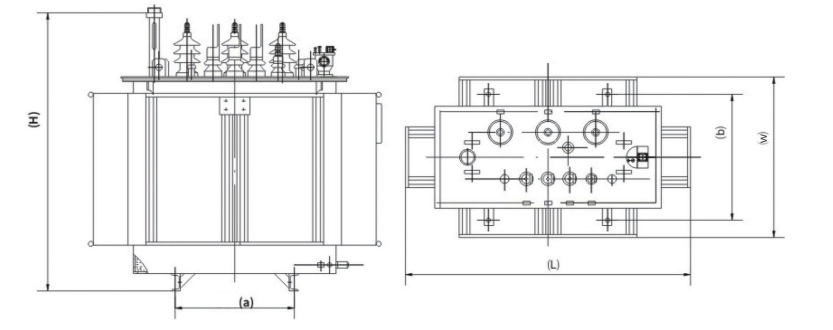
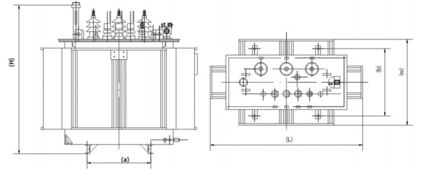
Rated Power (kVA) | Voltage (kV) | Vector Group | Impedance Voltage (%) | No-load Loss (W) | Load Loss (W) | No-load Current (%) | Reference Dimensions (mm) LWH | Total Weight (kg) |
| 30 | High Voltage (HV) Low Voltage (LV) | Dyn11 Yyn0 Yzn11 | 4 | 100 | 630/600 | 1,5 | 690x510x920 | 275 |
| 50 | 130 | 910/870 | 1.3 | 730x510x960 | 340 | |||
| 63 | 150 | 1090/1040 | 1.2 | 750x550x1000 | 385 | |||
| 80 | 180 | 1310/1250 | 1.2 | 790x620x1020 | 450 | |||
| 100 | 200 | 1580/1500 | 1.1 | 790x700x1040 | 520 | |||
| 125 | 240 | 1890/1800 | 1.1 | 840x800x1070 | 625 | |||
| 160 | 280 | 2310/2200 | 1.0 | 1070x670x1130 | 695 | |||
| 200 | 340 | 2370/2600 | 1.0 | 1140x750x1140 | 795 | |||
| 250 | 400 | 3200/3050 | 0,9 | 1200x800x1190 | 955 | |||
| 315 | 480 | 3830/3650 | 0,9 | 1300x860x1210 | 1085 | |||
| 400 | 570 | 4520/4300 | 0,8 | 1380x900x1240 | 1290 | |||
| 500 | 680 | 5410/5100 | 0,8 | 1450x950x1300 | 1590г . | |||
| 630 | Dyn11 Yyn0 | 4,5 | 810 | 6200 | 0,6 | 1500x970x1360 | 1850г. | |
| 800 | 980 | 7500 | 0,6 | 1660x1140x1400 | 2210 | |||
| 1000 | 1150 | 10300 | 0,6 | 1690x1190x1530 | 2570 | |||
| 1250 | 1360 | 12000 | 0,5 | 1760x1230x1600 | 3115 | |||
| 1600 | 1640 г. | 14500 | 0,5 | 1800x1250x1660 | 3520 | |||
| 2000 г. | 5 | 1940 год | 18300 | 0,4 | 1930x1360x1490 | 4060 | ||
| 2500 | 2290 | 21200 | 0,4 | 2080x1360x1570 | 5105 |
2. Three-phase oil-immersed distribution transformer S13-M, 10 kV.
Rated Power (kVA) | Voltage (kV) | Vector Group | Impedance Voltage (%) | No-load Loss (W) | Load Loss (W) | No-load Current (%) | Reference Dimensions (mm) LWH | Total Weight (kg) |
| 30 | High Voltage (HV) Low Voltage (LV) | Dyn11 Yyn0 Yzn11 | 4 | 80 | 630/600 | 1,5 | 695x490x860 | 260 |
| 50 | 100 | 910/870 | 1.3 | 725x520x955 | 365 | |||
| 63 | 110 | 1090/1040 | 1.2 | 750x535x970 | 415 | |||
| 80 | 130 | 1310/1250 | 1.2 | 770x565x985 | 465 | |||
| 100 | 150 | 1580/1500 | 1.1 | 800x595x1000 | 545 | |||
| 125 | 170 | 1890/1800 | 1.1 | 815x670x1010 | 585 | |||
| 160 | 200 | 2310/2200 | 1.0 | 1015x645x1055 | 695 | |||
| 200 | 240 | 2370/2600 | 1.0 | 1020x650x1115 | 810 | |||
| 250 | 290 | 3200/3050 | 0,9 | 1140x730x1120 | 930 | |||
| 315 | 340 | 3830/3650 | 0,9 | 1195x785x1175 | 1075 | |||
| 400 | 410 | 4520/4300 | 0,8 | 1265x855x1195 | 1255 | |||
| 500 | 480 | 5410/5100 | 0,8 | 1325x915x1240 | 1435 | |||
| 630 | Dyn11 Yyn0 | 4,5 | 570 | 6200 | 0,6 | 1465x960x1295 | 1880 г. | |
| 800 | 700 | 7500 | 0,6 | 1515x995x1340 | 2145 | |||
| 1000 | 830 | 10300 | 0,6 | 1605x1095x1460 | 2455 | |||
| 1250 | 970 | 12000 | 0,5 | 1685x1145x1485 | 2840 | |||
| 1600 | 1170 | 14500 | 0,5 | 1775x1225x1580 | 3310 | |||
| 2000 г. | 5 | 1550 г. | 18300 | 0,4 | 1855x1265x1600 | 3960 | ||
| 2500 | 1830 г. | 21200 | 0,4 | 1885x1305x1780 | 4980 |
3.Three-phase oil-immersed distribution transformer S14-M, 10 kV.

Rated Power (kVA) | Voltage (kV) | Vector Group | Impedance Voltage (%) | No-load Loss (W) | Load Loss (W) | No-load Current (%) | Reference Dimensions (mm) LWH | Total Weight (kg) |
| 30 | High Voltage (HV) Low Voltage (LV) | Dyn11 Yyn0 Yzn11 | 4 | 80 | 505/480 | 1,5 | 785x710x880 | 370 |
| 50 | 100 | 730/695 | 1.3 | 800x730x940 | 480 | |||
| 63 | 110 | 870/830 | 1.2 | 815x720x970 | 535 | |||
| 80 | 130 | 1050/1000 | 1.2 | 830x740x990 | 580 | |||
| 100 | 150 | 1260/1200 | 1.1 | 875x790x1010 | 705 | |||
| 125 | 170 | 1510/1440 | 1.1 | 875x770x1050 | 775 | |||
| 160 | 200 | 1850/1760 | 1.0 | 935x820x1140 | 975 | |||
| 200 | 240 | 2180/2080 | 1.0 | 995x870x1140 | 1140 | |||
| 250 | 290 | 2560/2440 | 0,9 | 995x900x1180 | 1240 | |||
| 315 | 340 | 3060/2920 | 0,9 | 1030x880x1250 | 1425 | |||
| 400 | 410 | 3610/3440 | 0,8 | 1075x910x1270 | 1635 г. | |||
| 500 | 480 | 4330/4120 | 0,8 | 1120x930x1320 | 1950 год | |||
| 630 | Dyn11 Yyn0 | 4,5 | 570 | 4960 | 0,6 | 1165x950x1350 | 2150 | |
| 800 | 700 | 6000 | 0,6 | 1210x1050x1390 | 2515 | |||
| 1000 | 830 | 8240 | 0,6 | 1520x1020x1450 | 2635 | |||
| 1250 | 970 | 9600 | 0,5 | 1630x1090x1540 | 3210 | |||
| 1600 | 1170 | 11600 | 0,5 | 1680x1150x1600 | 3905 | |||
| 2000 г. | 5 | 1550 г. | 14600 | 0,4 | 1890x1300x1600 | 4130 | ||
| 2500 | 1830 г. | 16900 | 0,4 | 1990x1360x1700 | 5250 |
1.S13-35 kV Technical Parameters of No-Load Tap-Changing Voltage Regulation Transformer
| Rated Power (kVA) | High Voltage (kV) | Tap Range | Low Voltage (kV) | Vector Group | Impedance Voltage (%) | No-load Loss (W) | Load Loss (W) | No-load Current (%) |
| 50 | 35 38,5 | ±2x2,5% ±5% | 0,4 | Dyn11 Yyn0 | 6,5 | 160 | 1200/1140 | 1.3 |
| 100 | 230 | 2010/1910 | 1.1 | |||||
| 125 | 270 | 2370/2260 | 1.1 | |||||
| 160 | 280 | 2820/2680 | 1.0 | |||||
| 200 | 310 | 3320/3160 | 1.0 | |||||
| 250 | 400 | 3950/3760 | 0,95 | |||||
| 315 | 480 | 4750/4530 | 0,95 | |||||
| 400 | 580 | 5740/5470 | 0,85 | |||||
| 500 | 680 | 6910/6580 | 0,85 | |||||
| 630 | 830 | 7860 | 0,65 | |||||
| 800 | 980 | 9400 | 0,65 | |||||
| 1000 | 1150 | 11500 | 0,65 | |||||
| 1250 | 1400 | 13900 | 0,6 | |||||
| 1600 | 1690 г. | 16600 | 0,6 | |||||
| 2000 г. | 1990 год | 19700 | 0,55 | |||||
| 2500 | 2360 | 23200 | 0,55 |
2.S13-35 kV Technical Parameters of No-Load Tap-Changing Transformer
| Rated Power (kVA) | High Voltage (kV) | Tap Range | Low Voltage (kV) | Vector Group | Impedance Voltage (%) | No-load Loss (W) | Load Loss (W) | No-load Current (%) |
| 630 | 35 | ±2×2,5% ±5% | 3.15 6.3 10,5 | Ярд11 | 6,5 | 830 | 7860 | 0,65 |
| 800 | 980 | 9400 | 0,65 | |||||
| 1000 | 1150 | 11500 | 0,65 | |||||
| 1250 | 1400 | 13900 | 0,55 | |||||
| 1600 | 1690 г. | 16600 | 0,45 | |||||
| 2000 | 2170 | 18300 | 0,45 | |||||
| 2500 | 2560 | 19600 | 0,45 | |||||
| 3150 | 35~38,5 | ±2×2,5% ±5% | 3.15 6.3 10,5 | 7.0 | 3040 | 23000 | 0,45 | |
| 4000 | 3610 | 27300 | 0,45 | |||||
| 5000 | 4320 | 31300 | 0,45 | |||||
| 6300 | 8.0 | 5240 | 35000 | 0,45 | ||||
| 8000 | 35~38,5 | ±2×2,5% | 3.15 3.3 6.3 6.6 10,5 | YNd11 | 7200 | 38100 | 0,35 | |
| 10000 | 8700 | 45300 | 0,35 | |||||
| 12500 | 10000 | 53800 | 0,3 | |||||
| 16000 | 12100 | 65800 | 0,3 | |||||
| 20000 | 14400 | 79500 | 0,3 | |||||
| 25000 | 10,0 | 17000 | 94000 | 0,25 | ||||
| 31500 | 20200 | 112000 | 0,25 |
3.S13-35 kV Technical Parameters of On-Load Tap-Changer (OLTC) Device
| Rated Power (kVA) | High Voltage (kV) | Tap Range | Low Voltage (kV) | Vector Group | Impedance Voltage (%) | No-load Loss (W) | Load Loss (W) | No-load Current (%) |
| 2000 | 35 | ±3×2,5% | 6.3 10,5 | YArd11 | 6,5 | 2300 | 19200 | 0,5 |
| 2500 | 2720 | 20600 | 0,5 | |||||
| 3150 | 35~38,5 | 6.3 10,5 | 7.0 | 3230 | 24700 | 0,5 | ||
| 4000 | 3870 | 29100 | 0,5 | |||||
| 5000 | 4640 | 34200 | 0,5 | |||||
| 6300 | 8.0 | 5630 | 36700 | 0,5 | ||||
| 8000 | 35~38,5 | 6.3 6.6 10,5 | YNd11 | 7870 | 40600 | 0,4 | ||
| 10000 | 9280 | 48000 | 0,4 | |||||
| 12500 | 1090 | 56800 | 0,35 | |||||
| 16000 | 1310 | 70300 | 0,35 | |||||
| 20000 | 1550 г. | 82100 | 0,35 | |||||
| 25000 | 10,0 | 1830 г. | 97800 | 0,3 | ||||
| 31500 | 2180 | 116000 | 0,3 |
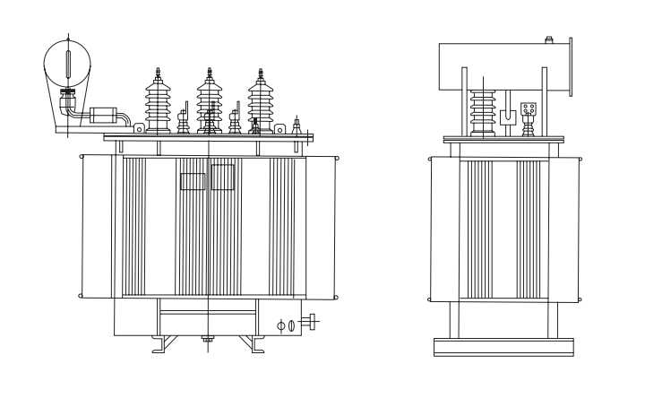
Outline Drawing

Oil Transformer Product Series
Related Electrical Equipment
We warmly welcome international clients to our facility. During their visit, they have the opportunity to tour our production workshops and witness firsthand the manufacturing and testing processes of transformers and switchgear equipment.
By observing our modern production capabilities, strict quality control, and professional technologies, clients gain a deeper understanding of our expertise and reliability. These visits not only strengthen trust but also lay a solid foundation for long-term cooperation and mutual development.
Our Participation in Exhibitions
We actively participate in leading industry exhibitions, showcasing our high-quality electrical solutions, innovative technologies, and reliable equipment. At our company booths, visitors can explore new products in detail, receive professional consultations, and discuss potential collaboration opportunities. Our experts are always ready to share their experience and demonstrate the advantages of our solutions.


About Us

Chenyuan Electric is a rapidly growing company with over 15 years of experience in the production and service of electrical power equipment. We are your reliable partner in the field of electrical installation equipment!
In 2019, we established a strategic partnership with Schneider Electric. Gradually expanding our production capacity, we provide comprehensive support for business development. Our factory includes multiple automated production workshops and fully equipped warehouse facilities. The modern European equipment installed in our workshops allows us to manufacture products that meet EU standards.
We hold CE, ISO, and EAC certifications. Our company is an official Schneider Electric partner, authorized to sell original equipment and produce Schneider-certified switchgear cabinets.
We invite you to visit our factory to discuss cooperation and explore potential partnership opportunities.
In the capital of Uzbekistan, Tashkent, we operate an official representative office (a Chinese company with 100% foreign capital). Our team includes qualified engineers ready to provide prompt consultation and offer optimal one-stop solutions.
Thanks to years of development, we have established a professional overseas service team, enabling us to respond quickly to customer requests. We continuously improve our cooperation approach, offering consultation during preliminary negotiations, production monitoring, after-sales service, and customized solutions.
Our core principle is: quality first, reputation foremost. We sincerely look forward to long-term and mutually beneficial cooperation!
Industry Solutions
We are a key supplier for major state projects, such as the State Power Grid Corporation, the State Railway Administration, and the South-to-North Water Diversion Project. Our products are widely used in power systems, state projects, mining, metallurgy, real estate, and renewable energy sectors. Additionally, our products are exported to countries including Russia, Kazakhstan, Tajikistan, Uzbekistan, and others.

Certifications
All transformers have passed CE, IEC, GOST, and other certifications.
